
Surround and Spatial Sound Microphone Techniques
by Larry Seiler
The advent of surround sound, and more recently that of spatial (immersive) sound has created the need for recording methods that go beyond those microphone techniques used for stereo recording. Many of the techniques used to capture a surround sound recording of a group, such as a choir, orchestra, or other ensemble, are adaptations or extensions of stereo microphone techniques. We will cover surround sound techniques first. Surround recording techniques can be divided into four categories: (1) those that use a front array of microphones placed in close proximity, (2) those having separate front and rear arrays, (3) special arrays developed specifically for recording just the ambience of a space, which are used in conjunction with a front array, and (4) microphone arrays assembled as a unit.
Front Arrays
The front arrays are basically stereo microphone techniques used to capture the main stereo image of the musical ensemble. The well-known Decca tree method is the same technique that has been used for years to make stereo recordings. The other front arrays are similar to the Decca tree using a variety of microphones, angles, and spacing. For surround sound, the front arrays normally are used in conjunction with an ambience array, which will be discussed later as will various combinations of front and rear arrays.
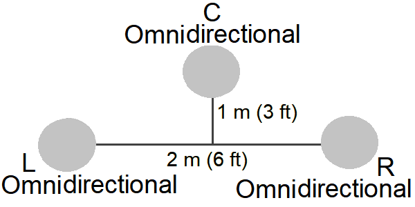
Decca Tree
The Decca tree is a stereo microphone technique developed by Roy Wallace and Arthur Haddy at Decca Studios in London in the 1950s, and has been used for years for stereo recording of orchestras. It uses three omnidirectional microphones in a triangle. Two microphones are placed left and right approximately 2 m (6 ft) apart with the third placed in the center about 1 m (3 ft) in front, and approximately 2.5 - 3 m (8 - 10 ft) up. The side mics are panned hard left and right while the third mic is mixed dead center. This technique produces a strong stereo image. It is sometimes called A-B-C stereo.1
INA-3 or Ideal Cardioid Arrangement (ICA)
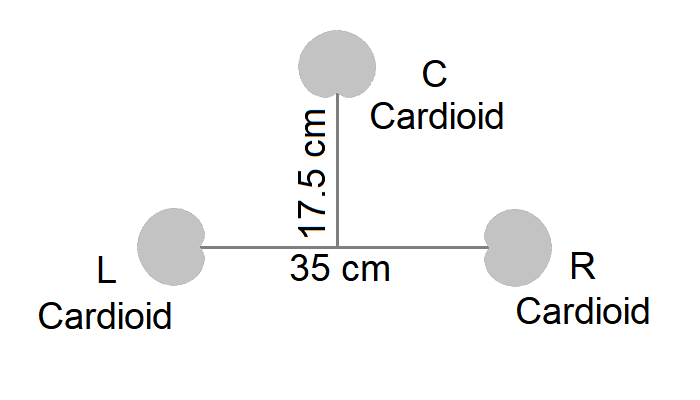
Ideal Cardioid Arrangement (ICA)
This microphone technique was developed by Günther Theile. INA is an acronym for Ideale Nieren Anordnung, German for “ideal cardioid arrangement,” and it is sometimes called by that name. The INA-3 is a technique for the three-microphone front array, and most commonly is used with the rear array in the INA-5, which is discussed below. The INA-3 uses a cardioid microphone for the center channel placed 17.5 cm (7 in) in front of two cardioids used for left and right channels, pointing outwards. The spacing between the left and right microphones is 35 cm (14 in). Distances between the front three microphones can be changed to adjust the ambient response.8
Optimized Cardioid Triangle (OCT)
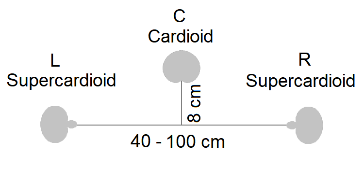
The optimized cardioid triangle technique was developed by Günther Theile and Helmut Wittek for the front microphone array. It uses three microphones in a triangle with the center cardioid mic facing forward about 8 cm (3 inches) in front of the two higher side supercardioid mics that face outward about 40 to 100 cm (about 15 to 40 in) apart, with recording angles from 160° to 90°. It produces high separation between left-center and right-center and good localization.2
Omni+8
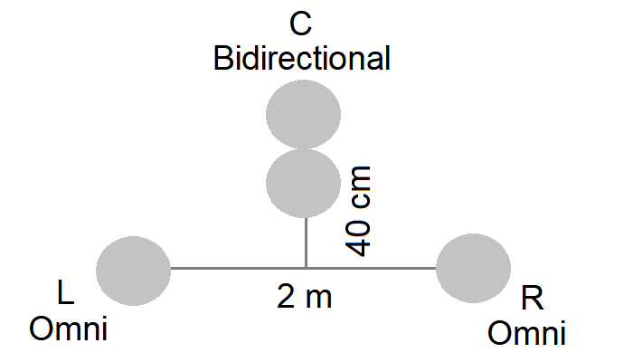
Omni+8 is a microphone technique for the front microphone array, typically used with the Omini+8 surround technique, discussed below. It consists of two omnidirectional microphones spaced 2 meters (6.5 ft) apart for left and right, and a figure-eight microphone for the center placed 40 cm (16 in) forward. The omnidirectional mics provide a rich and extended impression with ample bass response, while the figure-eight mic provides a strong, stabilized center channel.10
The Disadvantage of Three-Microphone Techniques
While three-microphone techniques work great for traditional two-channel stereo, there is a problem when mixing it down to the three channels (L-C-R) used in surround sound. When a three-microphone recording is played back through speakers, it can create a “triple phantom sound source.” Because of interchannel crosstalk, each two-channel pair (C-L, C-R, and L-R) produces a different phantom image, which seems to move as the listening position changes, leading to loss of focus and clarity.3 Despite this problem many people still claim excellent results with these techniques. However, the following two somewhat lesser known techniques were designed to overcome this shortcoming.
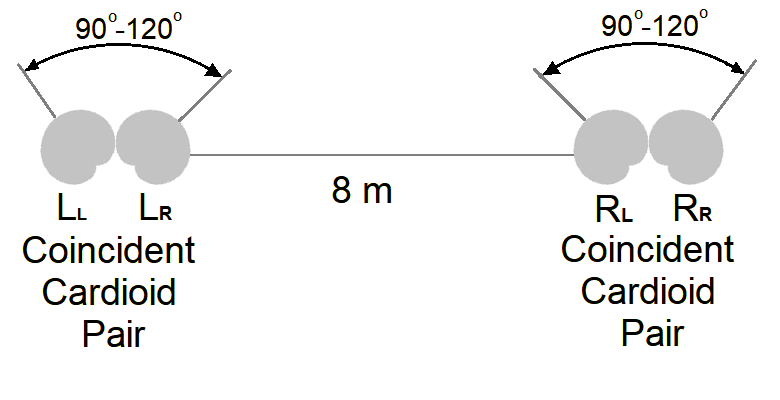
Double X-Y
The double X-Y method is an extension of the X-Y stereo technique that uses two coincident pairs. Each pair of cardioid microphone are angled at 90° to 120° from each other and are placed approximately 8 m (26 ft) apart. This technique works well for recording large orchestras, because the large distance results in minimal crosstalk between the left and right channels. However, it is not very effective for recording small groups or individual instruments such as a piano. The three channels are derived as follows: LL and RR are panned left and right. The center channel is the sum of LR plus RL, reduced by 3dB. This method is sometimes called a multiple X-Y technique.3
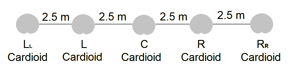
Double A-B
The double A-B method is an extension of the spaced cardioid stereo technique. (The original A-B stereo technique used omnidirectional microphones.) It uses five cardioid microphones spread in a line across the width of the stage, with the distance between each mic in the range of about 2.5 m (8 ft). This technique reduces the multiple phantom sound source problem. However, this technique is only useful for large ensembles. The three channels are derived as follows: Left channel = LL + L (reduced 3 dB), right channel = RR + R (reduced 3 dB), and center channel = C + L (reduced 3 dB) + R (reduced 3 dB). This method is sometimes called a multiple A-B technique.3
Ambience Arrays
These are specialized arrays designed to capture the ambience in a space. They are normally used in conjunction with one of the front arrays described above.
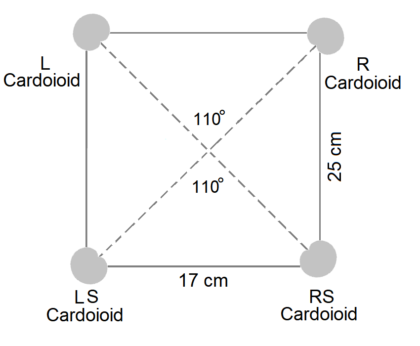
Double ORTF
The double ORTF is an ambience technique based on the ORFT (Office de Radiodiffusion-Television Francaise) stereo technique. It consists of four cardioid microphones placed in a rectangular formation, with front and rear arrays angled at 110 degrees from one another and 17 cm (7 in) apart. The rear array is 25 cm (10 in) behind the front array. It is essentially two ORTF configurations placed back-to-back. Compare with the IRT cross, which some people have claimed as being a double ORTF.6
Hamasaki Square
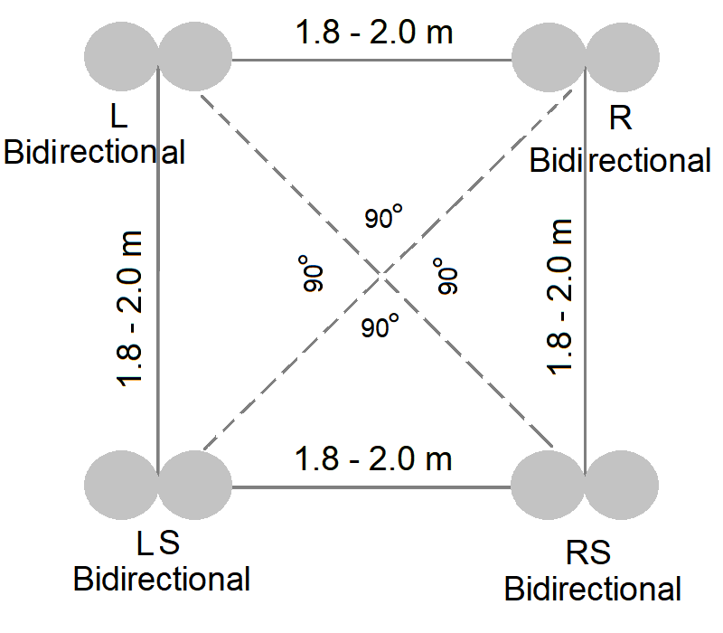
The Hamasaki square is a ambience technique developed by Kimio Hamasaki, a research engineer with NHK Science & Technical Research Laboratories (STRL), which is a division of NHK (Nippon Hoso Kyokai), the Japan Broadcasting Corporation, Japan's national public broadcasting organization. It uses four bidirectional (figure-eight) microphones arranged in a square, spaced about 1.8 to 2 meters (6 to 6.5 ft) apart, facing outward with the microphone nulls pointing toward the main sound source so as to minimize the pickup of direct sound as well as the echoes from the back of the space. Ideally this array should be placed toward the back and high in the space. The back two microphones are mixed to the surround channels, while the front two channels are combined with the front left and front right signals. This technique is less sensitive to the distance between the main array and the ambience array than other ambience techniques. 9
IRT Cross
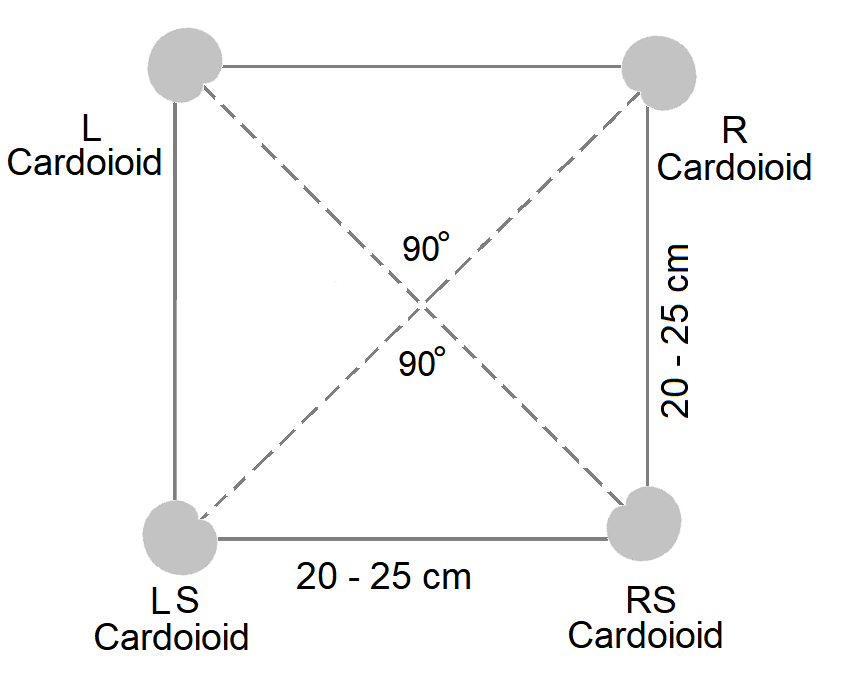
The IRT cross is a ambience technique developed by the German-based IRT (Institut für Rundfunktechnik — Institute of Radio Technology). It consists of four cardioid microphones placed in a square formation, angled at 90 degrees from one another, 45 degrees off axis from the sound source, and 20 to 25 cm (8 to 10 in) apart. The outputs from these mics are routed to left, right, left surround, and right surround at an appropriate level compared to the front mic array. The main disadvantage of this approach is that it has a significant amount of direct sound. This technique resembles back-to-back near-coincident stereo pairs. Although some people have called it a double ORTF, it does not use the ORTF angle of 110 degrees and it is slightly larger. 9
Combined Front and Rear Arrays
(Ideal Cardioid Arrangement
These techniques are complete surround sound techniques that consist of both the front array and the rear ambient array.
INA-5 or Ideal Cardioid Arrangement (ICA) Surround
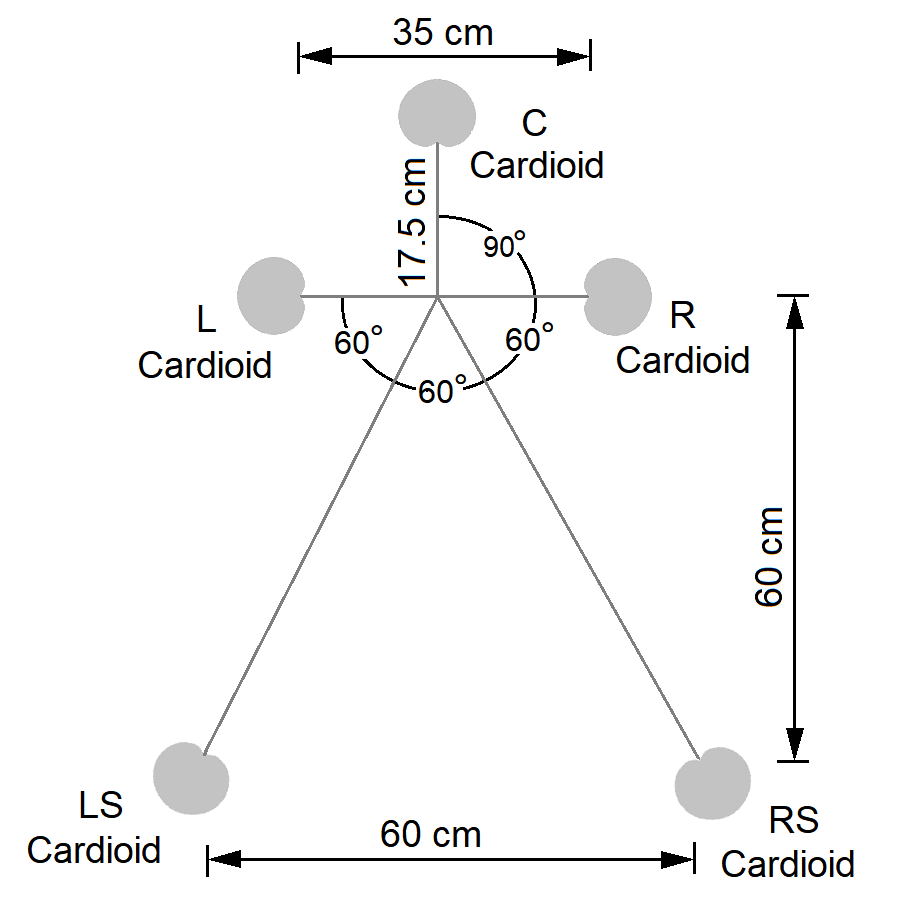
INA-5 is a surround sound microphone technique that is an extension of the three-channel INA-3 system developed by Günther Theile. It uses five cardioid microphones with the center microphone placed 17.5 cm (7 in) in front of two cardioids for left and right channels, pointing outwards. The left and right microphones are spaced 35 cm (14 in) apart. Two additional rear cardioid mics are placed about 60 cm (24 inches) behind the front line, and 60 cm (24 in) apart, with an angle of 150° from the center mic. Distances between the front three microphones can be changed to adjust the ambient response.8
Fukada Tree
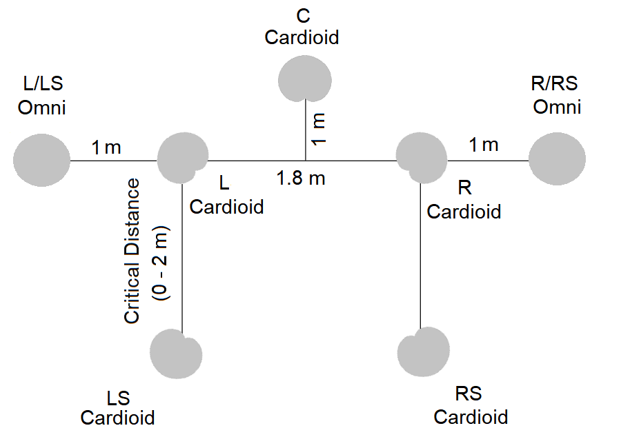
The Fukada tree was developed by Akira Fukada, a recording engineer with NHK STRL. The front array consists of three cardioid microphones arranged similar to a Decca tree, with two cardioids spaced 1.8 meters (6 ft) apart, and the center microphone placed 1 meter (40 in) forward, producing a strong center image. Two additional omnidirectional microphones can be added on the left and right to enlarge the perceived image size or to better consolidate the front and surround channels. The rear array consists of two cardioids spaced about 1.8 meters (6 ft) apart. The left and right mics are angled at 45° from the center microphone and the rear mics at 135°. The surround microphones are positioned at the critical distance, the point at which the direct sound and reverberant field is equal. The front array should be placed several meters above and behind the conductor.2
Corey/Martin Tree
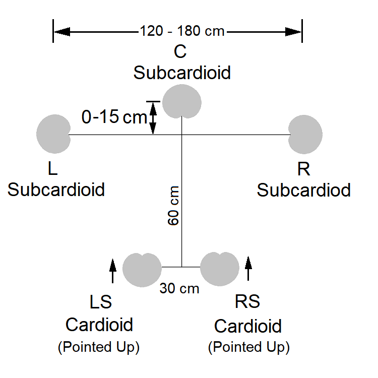
The Corey/Martin tree is a surround sound microphone technique designed by Jason Corey and Geoff Martin consisting of three subcardioid microphones facing the front, and two cardioid microphones behind them facing the ceiling. The distance between the left and right front mics is 120 cm (48 in) with the center mic halfway between them. The rear surround cardioids are 30 cm (12 in) apart and about 60 cm (24 in) behind the front pair. The center microphone can be moved forward up to 15 cm (6 in), if needed. These distances can be adjusted depending on the size of the ensemble being recorded. A front spacing of 120 cm (48 in) is used for smaller ensembles, increasing to 180 cm (6 ft) for larger groups. However, with wider spacing the three front channels become more incoherent.8
Wide Cardioid Surround Array (WCSA)
A variation of Corey/Martin tree technique, developed by Mikkel Nymand, is called the Wide Cardioid Surround Array. It uses matched cardioid microphones. This array is supposed to create an intense, dynamic, and enveloping sound character.4
Hamasaki System
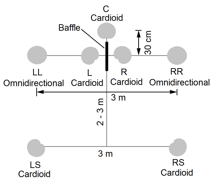
The Hamasaki surround system, which also called the NHK surround system, was developed by Kimio Hamasaki, a research engineer with NHK STRL. It uses 5 cardioid and two omnidirectional microphones. A baffle is used to separate the left front and right front channels, which are 30 cm (12 in) apart and angled at 45 degrees. Two omnidirectional microphones, which are low-pass filtered at 250 Hz, are spaced 3 meters (10 ft) apart in line with the left and right cardioids. The center mic is placed about 30 cm (12 in) forward. The rear pair of cardioids are placed 2 to 3 meters (6 to 10 ft) behind front array and 3 meters (10 ft) apart, at an angle of 135°.2
Double Mid-Side
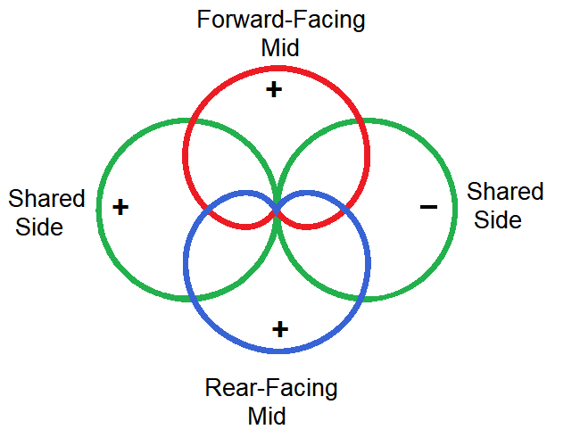
The double mid-side (M-S) technique is the mid-side stereo microphone technique expanded to surround sound. It uses two cardioid microphones, one facing front and one facing backward, each shared with one side-facing figure-eight microphone. The recorded tracks can be decoded by sums and differences of the microphone signals into the left front, right front, left side, and right side. This technique also allows for post recording changes to the pickup angle. Many of the other surround sound techniques occupy a considerable amount of space, making them inconvenient for field recording. However, the double mid-side technique is quite compact.2
Polyhymnia Pentagon
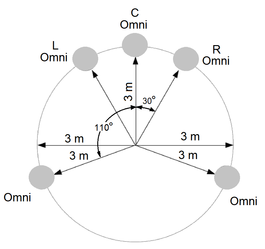
The Polyhymnia pentagon was developed by Polyhymnia International (a recording company formerly known as Philips Classics). Five omnidirectional microphones are arranged according to the loudspeaker arrangement defined in ITU-R BS775, with the recorded signal from each microphone being panned into a corresponding speaker from this recommendation. The five microphones are placed on a circle with a radius of 2 meters (6.5 ft). The angle between the center mic and the left and right mics is 30°. The angle between the center and the surround mics is between 100 and 120°, with 110° being the most common setting. The length of the radius can be adjusted depending on the size of the ensemble, as well as the size of a room.8
Optimized Cardioid Triangle (OCT) Surround
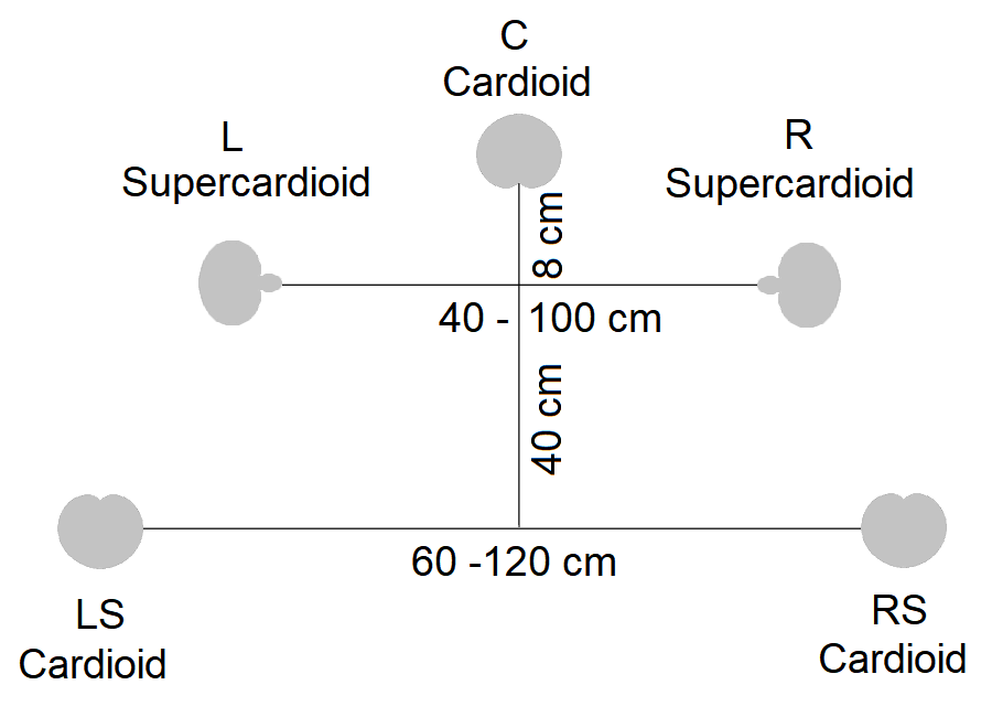
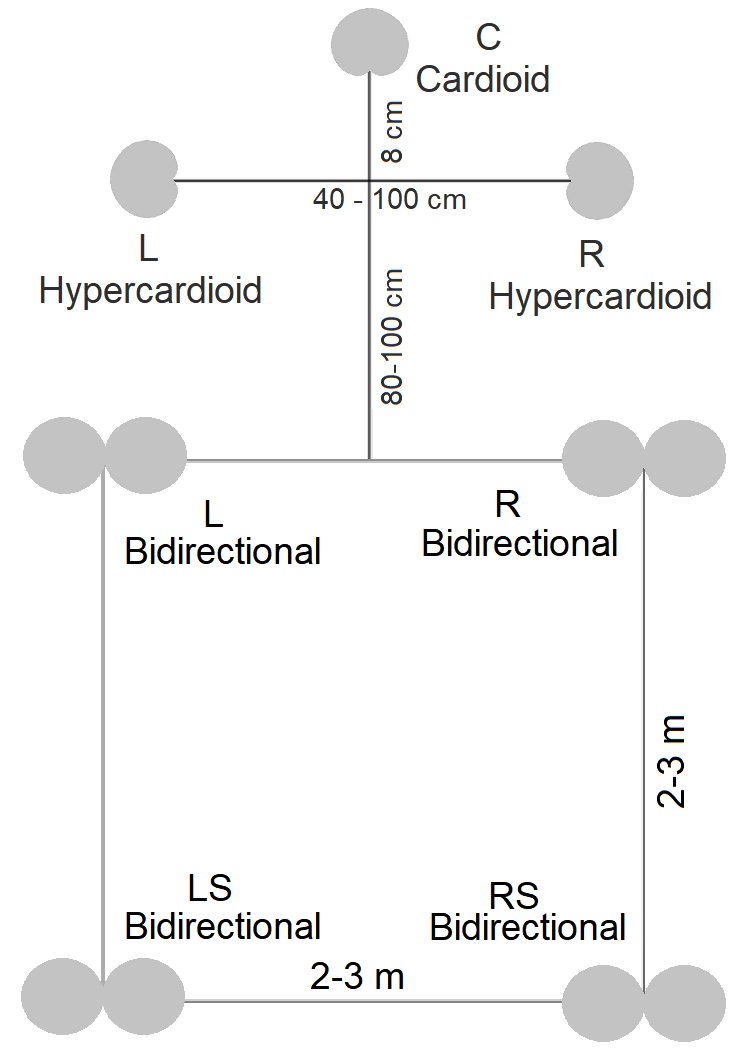
The OCT surround technique was developed by Dr. Günther Theile. It uses the OCT technique for the front array plus additional surround channel microphones. The front array is designed to minimize crosstalk, by using supercardioids for the front left and right microphones spaced 40 to 100 cm (15 to 40 in) apart, angled at 90 degrees from the center cardioid microphone, which is placed about 8 cm (3 inches) forward. Two additional rear cardioid mics are placed about 40 cm (15 inches) behind the front line and an additional 20 cm (8 inches) farther out, pointing toward the rear. It produces good separation in the front, good localization, and a large listening area with a natural-sounding effect.9
Perception Control Microphone Array (PCMA)
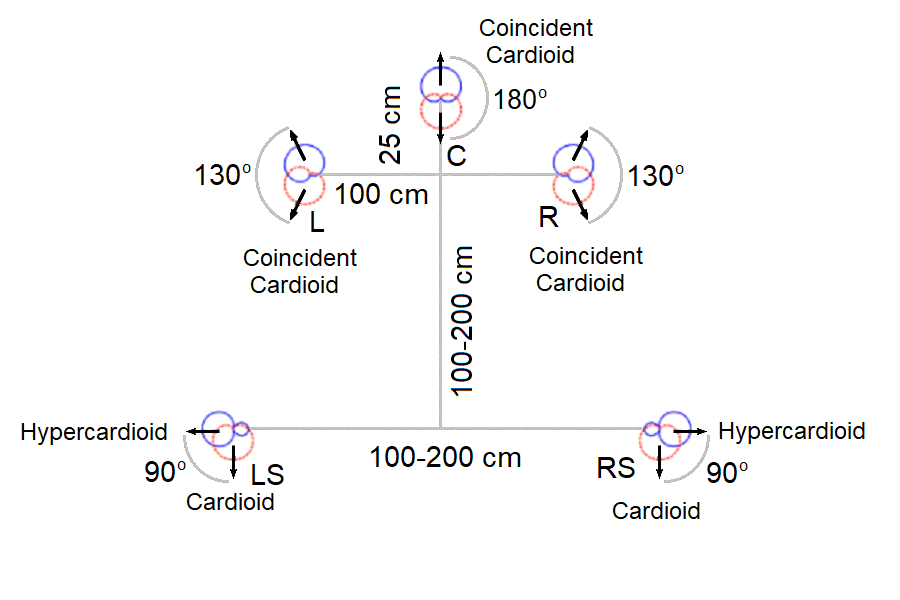
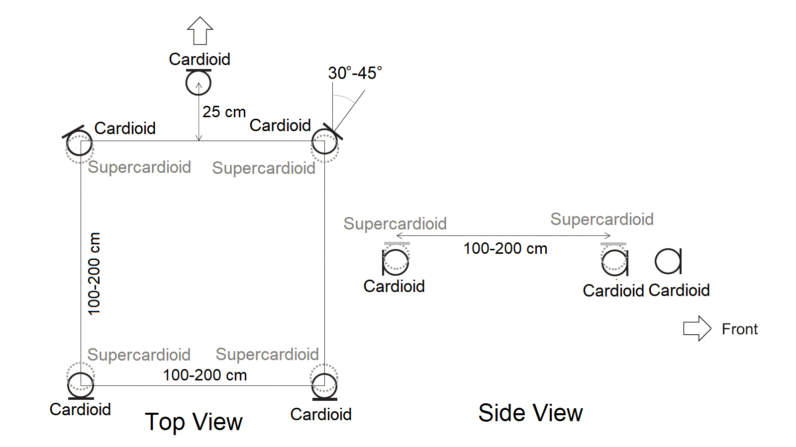
The Perception Control Microphone Array (PCMA) is a surround sound microphone array devised by Hyunkook Lee. It consists if five widely spaced coincident pairs of microphones. The left and right pair are spaced 100 cm (3.5 ft) apart. A center pair is located 25 cm (10 in) in front of the baseline. The rear microphone pairs are located 100 to 200 cm (39 to 78 in) behind the front microphones and 100 to 200 cm (39 to 78 in) apart. The center is a cardioid pair placed back-to-back (180°). The left and right front pairs are cardioid microphones, one facing forward and the other facing slightly rearward at 135°. The left and right rear pairs consist of hypercardioid microphones pointing outward and cardioid microphones facing backward (90°). Hypercardioid microphones are used to minimize the amount of direct sound. This array is designed to be as flexible as possible. The ratio of the signals from each microphone pair can be varied to control the direct to reverberant ratio. This technique allows the user the flexibility to render a variety of spatial audio images.19
Optimized Cardioid Triangle and Hamasaki Square (OCT+Hamasaki)
This is a surround sound microphone technique that combines the optimized cardioid triangle (OCT) technique front array with a Hamasaki square for the ambience channels. The OCT uses three microphones in a triangle with a center cardioid mic facing forward and two side supercardioid mics facing outward, similar to a modified Decca tree. The Hamasaki square uses four bidirectional (figure-eight) microphones arranged in a square, each facing outward with the microphone nulls pointing forward.
Optimized Cardioid Triangle and IRT Square (OCT+IRT)
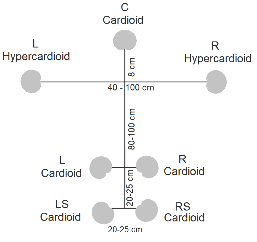
This is a surround sound microphone technique that combines the optimized cardioid triangle (OCT) technique front array with an IRT cross for the ambience channels. The OCT uses three microphones in a triangle with a center cardioid mic facing forward and two side supercardioid mics facing outward. The IRT cross consists of four cardioid microphones placed in a square formation, angled at 90° from one another and 45° off axis from the sound source.
Omni+8 Surround
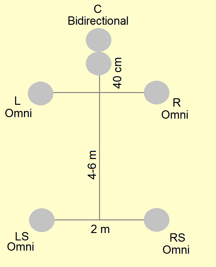
This technique is the surround version of the Omni+8 technique. It consists of two omnidirectional microphones spaced 2 meters (6.5 ft) apart for left and right, and a figure-eight microphone for the center placed 40 cm (16 in) forward. The left and right surround mics are omnidirectional microphones placed 4 to 6 meters (13 to 20 ft) behind the front array, and 2 meters (6.5 ft) apart. If there excessive room reflections, bidirectional (figure-eight) microphones may be substituted for the surround channels.10
Cardioid Trapezoid
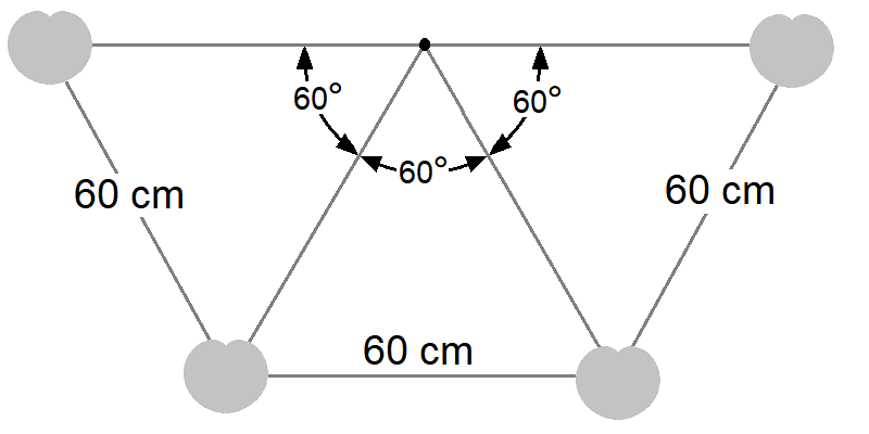
The cardioid trapezoid, known as the cardioid trapezium in the UK, is a surround technique especially designed for live pop music concerts, which do not require pickup of side reflections. It consists of four cardioid microphones facing backward, angled at 60° from one another, and 60 cm (2 ft) apart, in the shape of a trapezoid. It is effective for the pickup of both audience and ambience. Developed by Günther Theile, it is also known a Theile trapezoid.
Spatial Audio
Spatial audio, also called 3D audio, immersive audio, or immersive sound, can be considered an extension of surround sound. Whereas surround sound reproduces sound in two dimensions in a 360°-pattern around the listener, spatial audio reproduces sound in three dimensions. Sound is reproduced from all directions, the front, the back, the sides, as well as above and below the listener. As of this writing, there are four competing, but incompatible technologies providing spatial audio: Auro-3D, Dolby Atmos, Sony 360 Reality Audio, and DTS:X. While Auro 3D reproduces sound in which each channel uses a dedicated loudspeaker, Dolby Atmos, Sony 360, and DTS:X use audio objects, algorithms that send the sound in a particular direction, based on the speaker configuration.
There is another form of spatial audio called binaural audio. Binaural audio is a method of reproducing sound through headphones that uses a specially encoded stereo file that delivers a full three-dimensional soundscape. It models the way sound reflects around the head and within the ridges of the human ear. It is typically recorded with microphones that mimics the size and shape of a human head. Sound is reproduced in every direction, but the audio does not respond to user input. So, if you move your head, the audio does not move accordingly. This is referred to as “head-locked” audio. Techniques for recording binaural audio are usually very different from recording spatial audio.
While a “head-locked” environment is fine in a movie theatre, it does not work well for a virtual reality (VR) experience. You want a virtual world to be like the real world. For example, if you hear a bird singing in a tree to your left, you should hear that sound coming from the left, but if you turn your head to look at the bird, the sound should shift to be in front of you. For that reason VR uses something called 3D Spatial Audio. If done correctly, 3D spatial audio should convincingly place sounds in a three-dimensional space so that the user perceives the sounds as coming from the real physical objects in their VR experience. Methods for achieving this goal is beyond the scope of this article.
While spatial audio was developed primarily for use in movies, it has been adopted for recording music as well. This article will only discuss the techniques for recording music, although there is likely to be some overlap.
Dedicated Spatial Audio Microphones
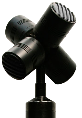
Tetrahedral Microphones
The tetrahedral microphone a device consisting of four closely spaced cardioid microphone capsules arranged in a tetrahedron, invented by Michael Gerzon and Peter Craven. It can function as a mono microphone, a stereo microphone, a surround sound microphone, or spatial audio microphone. The microphone produces four signals, called the A-Format that must be processed via software or hardware into a second set of signals called the B-Format. It is part of the Ambisonics surround sound technology, but is not exclusive to it.10 These microphones are sometimes called Ambisonic microphoness and sometimes are called a SoundField™ microphones, which is a trademark currently owned by RØDE. Beside RØDE, Sennheiser offers a tetrahedral microphone called the Sennheiser AMBEO VR Microphone. AMBEO™ is Sennheiser's trademark for 3D audio and its associated programs. Core Sound also offers OctoMic™, a second-order Ambisonic microphone, and TetraMic™, a first-order Ambisonic microphone. There are several other less-known Ambisonic microphones available.
Ball Boundary Microphone
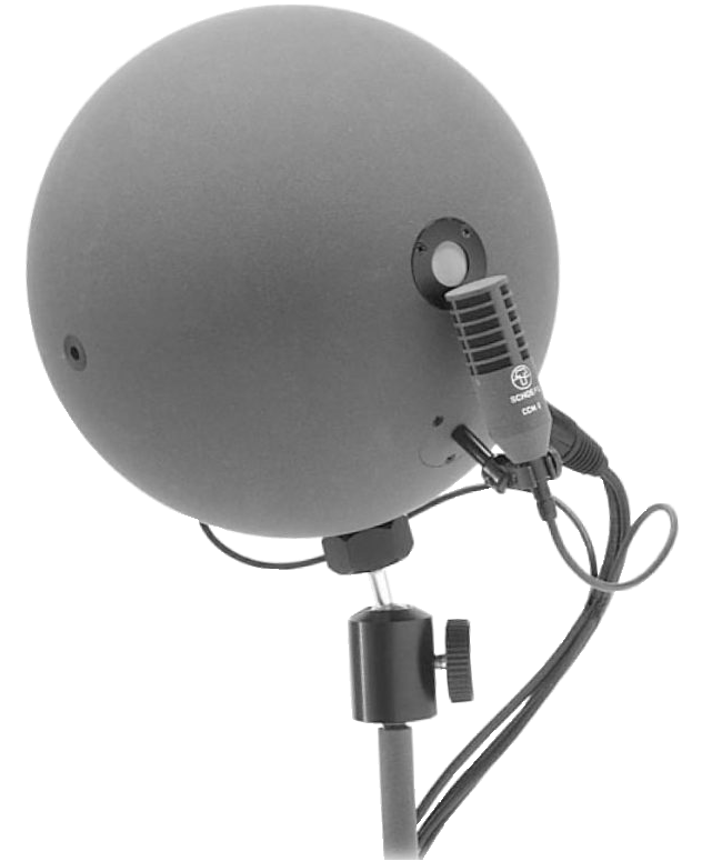
The ball boundary microphone consists of two bidrectional (figure-eight) microphones placed on each side of a sphere microphone facing the front. A sphere microphone has two condenser microphones flush-mounted in each side of a sphere to simulate a human head. The various channels are derived by combining the various signals as follows: Left = Ls + Lbi, Right = Rs + Rbi, Left Surround = Ls - Lbi, and Right Surround = Rs - Rbi, where Ls is the signal from the left sphere microphone, Rs is the signal from the right sphere microphone, Lbi is the signal from the left biderectional microphone, and Rbi is the signal from the right biderectional microphone.10
Microphone Array
Spherical Microphone Array
The spherical microphone array consists of a sphere into which are mounted a number of microphone capsules (as many as 24) pointed in a variety of directions, that are used to capture three-dimensional immersive sound of a live performance at a single point. The array includes processing to convert the multichannel sounds into some form of 3-D surround sound.
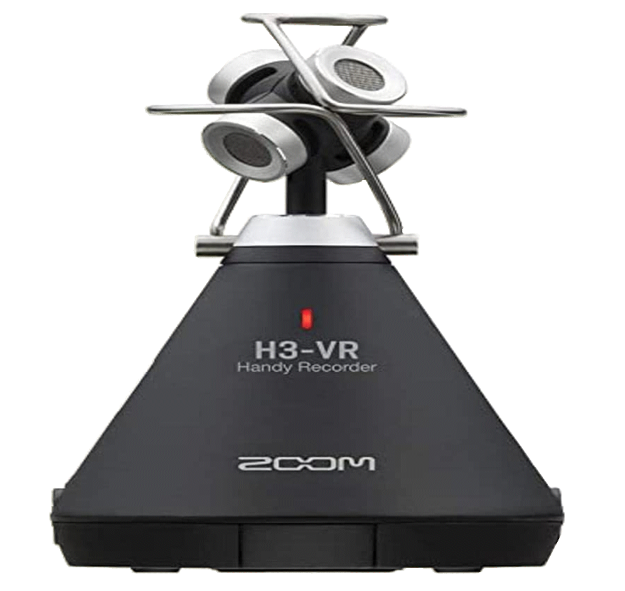
Hand-Held Recorder
A new entry in this category is a hand-held recorder with a bulit-in tetrahedral microphone. The Zoom H3-VR has a first-order ambisonic microphone, because it records four channels. Second-order ambisonic microphones have nine channels, but only four channels are needed to record spatial audio. While most systems need to be converted from raw A-Format audio to B-Format finished spatial audio, this device has the conversion process built in. 11
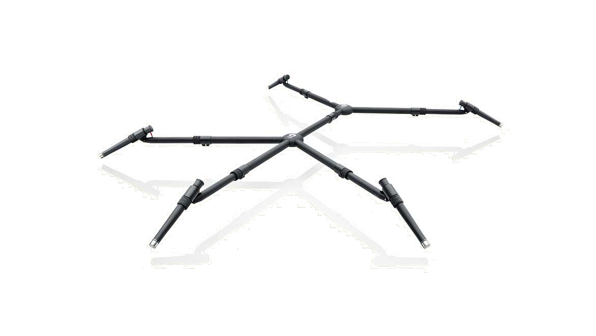
Spatial Audio Mounts
DPA Microphones sells a surround mount, designed to be used with pencil-style microphones, but according to DPA, can be adapted to other types as well. The mount is compact, lightweight, strong, and stable. A broad variety of surround microphone arrays can be set up using this mount, including OCT2, Hamasaki Square, Fukada Tree, and the WCSA (Wide Cardioid Surround Array). The main drawback is that it is somewhat expensive.
These microphone systems can work well for recording anything from small ensembles to large orchestras where you want to capture the three-dimensional sound field. There an especially good option when recording in small or tight spaces. The disadvantage of using ambisonic-type microphones is they do not create as realistic a spatial sound as do surround sound microphone array techniques. The tetrhedral microphones are trying to capture an entire acoustical space from essentially a single point in space.12
Spatial Audio Arrays
Spatial audio recording is really in its infancy. Many producers and studios are still experimenting and trying out new techniques. Many of the techniques are the same surround sound techniques described above with added mics for capturing height signals. Often the technique consist of to arrays one above the other. The lower layer, which is sometimes called the base, main, or middle layer, is designed to capture a surround image of the source. The upper layer, sometimes called the height layer, is designed to capture ambience or height signals. Below are some of techniques that are currently being used and sometimes still the subject of experimentation.
Black indicates the main layer
Grey indicates the upper layer
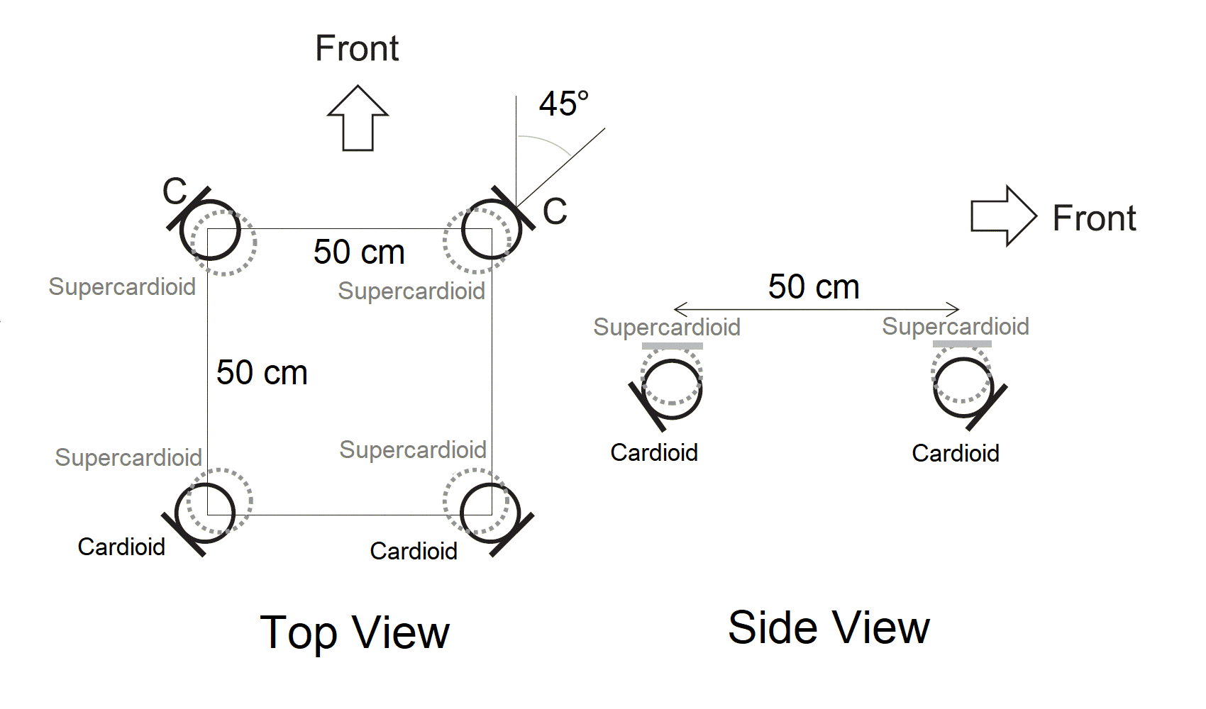
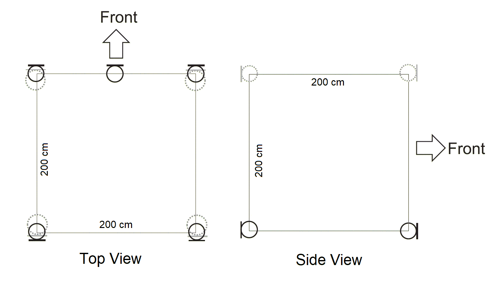
Equal Segment Microphone Array (ESMA)
The equal segment microphone array is a 3D microphone technique developed by Hyunkook Lee of Applied Psychoacoustics Laboratory (APL). It consists of eight microphones arranged in two layers, with each being laid out in a 50-cm (20-in) square. The bottom layer, responsible for capturing the main sound sources, consists of four cardioid microphones angled at 90° between pairs. The upper layer is coincident with the bottom layer (0 spacing) and consists of four supercardioid microphones aimed upward to capture ambience and elevated sources. This array provides very good spaciousness with an accurate and stable image, both vertically and horizontally.14
Black indicates the main layer
Grey indicates the upper layer
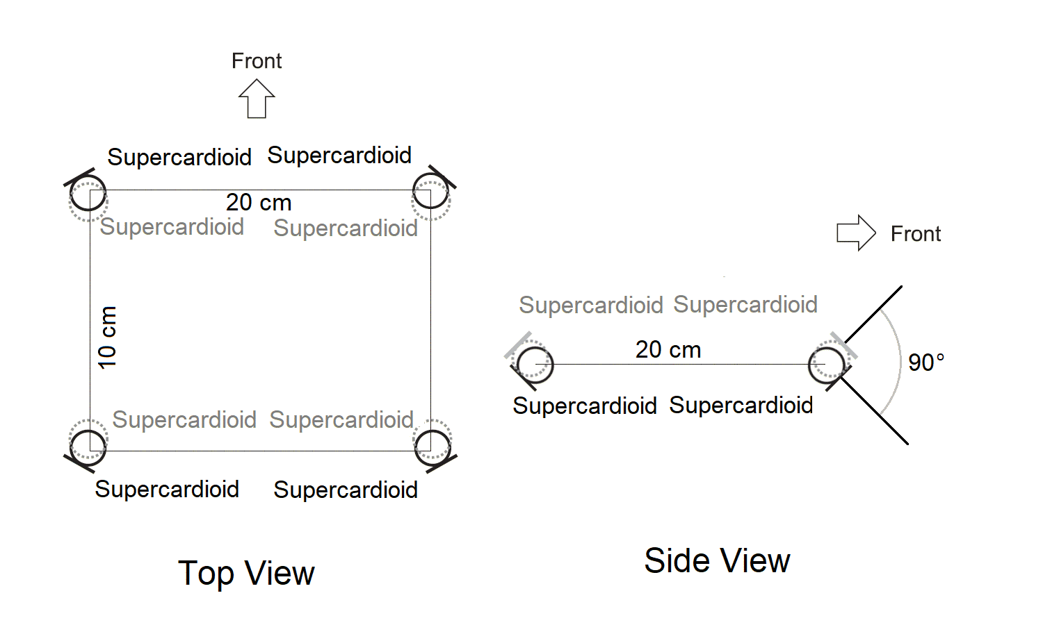
ORTF-3D
ORTF-3D is a 3D microphone array developed by Helmut Wittek and Günter Theile that essentially places two ORTF Surround systems onto two planes. It consists of two layers arranged in 10-cm x 20-cm (4-in x 8-in) rectangles placed directly above each other. Each layer has four supercardioid microphones, which are tilted upward or downward to create signal separation in the vertical plane. Signals are routed to four channels for the lower layer (L, R, LS, and RS) and four for the upper layer (Lh, Rh, LSh, and RSh). ORTF-3D produces spatially open and stable 3D recordings. It features very good 360° imaging with a pleasant, natural-sounding spatial impression and a large listening area.16 Schoeps offers a ORTF-3D setup with microphones designed for outdoor use.
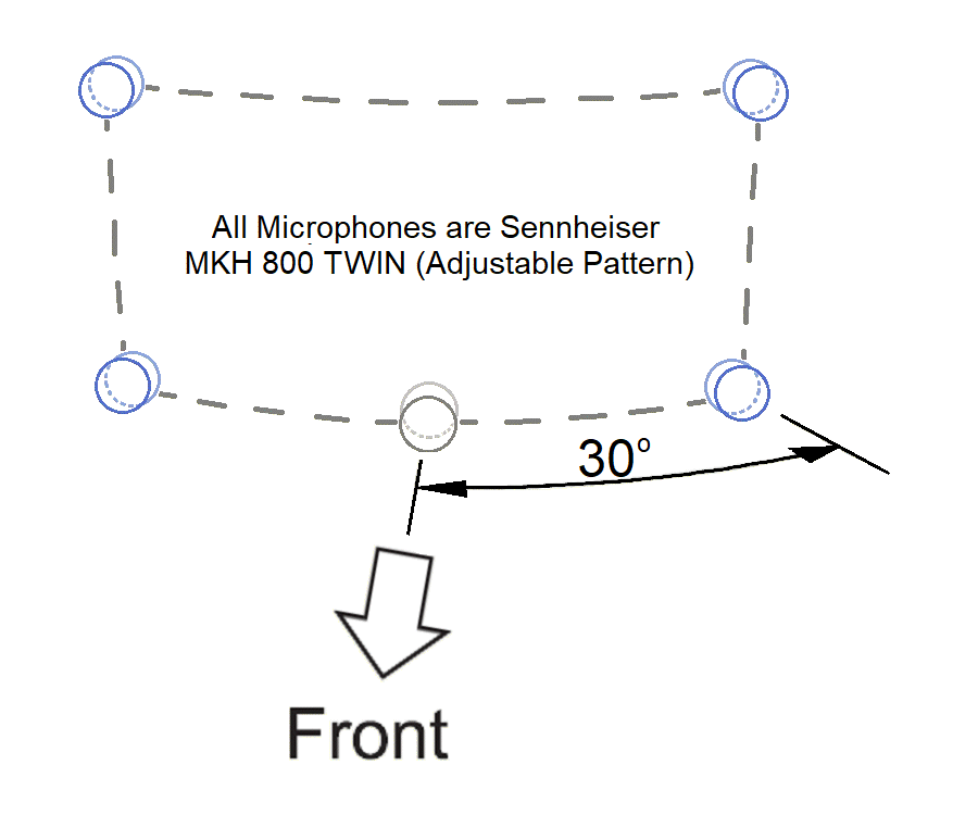
Twins Square (AMBEO Square)
The Twins Square is a 3D microphone technique developed by Gegor Zielinsky of Sennheiser, who calls it an AMBEO square. It consists of four microphones arranged in a vertical square, with one microphone facing forward at each corner. An optional fifth microphone may be located halfway between the bottom two microphones. Sennheiser does not provide any distance specs, but does specify an angle of 30° from the center on each side. Sennheiser specifies using their MKH 800 TWIN microphones. The MKH 800 Twin is a condenser microphone containing two opposite-facing, cardioid capsules. The dual signals from each transducer pair can be sent out separately as discrete outputs.20 This design provides the capability of adjusting the polar pattern remotely, either during recording or after the fact during mixing.15 According to Sennheiser, this is the simplest and most efficient set-up for recording immersive music.16
Black indicates the main layer
Grey indicates the upper layer
Twins Cube (AMBEO Cube)
The Twins Cube is a 3D microphone technique, developed by Gegor Zielinsky of Sennheiser, who calls it an AMBEO cube. It expands the Twins Square by placing a second Twins Square array behind the first to create a cube.13 It has nine microphones in two layers with each containing four microphones. The four lower microphones are setup at a selected distance apart, at angles of 30° and 110° from the center. The four upper microphones are placed directly above the four lower microphones at half the distance. The ninth microphone is placed in the front center of the lower layer in the same plane. Sennheiser specifies their MKH 800 TWIN condenser microphones for all nine microphones. The Twins Cube array is designed to mirror the 9.1 loudspeaker configuration.20 The company says this is probably the best and most flexible way of recording music in spatial audio.17
AMBEO Lean Cube
The AMBEO Lean Cube is a 3D microphone technique developed by Gegor Zielinsky of Sennheiser that uses the same setup as the AMBEO Cube, but uses the MKH 8090 wide cardioid instead of the MKH 800 TWIN. You have option of using the MKH 8090s for the rear and MKH 800 TWIN for the front microphones or using MKH 8090s on all microphone positions.13
Black indicates the main layer
Grey indicates the upper layer
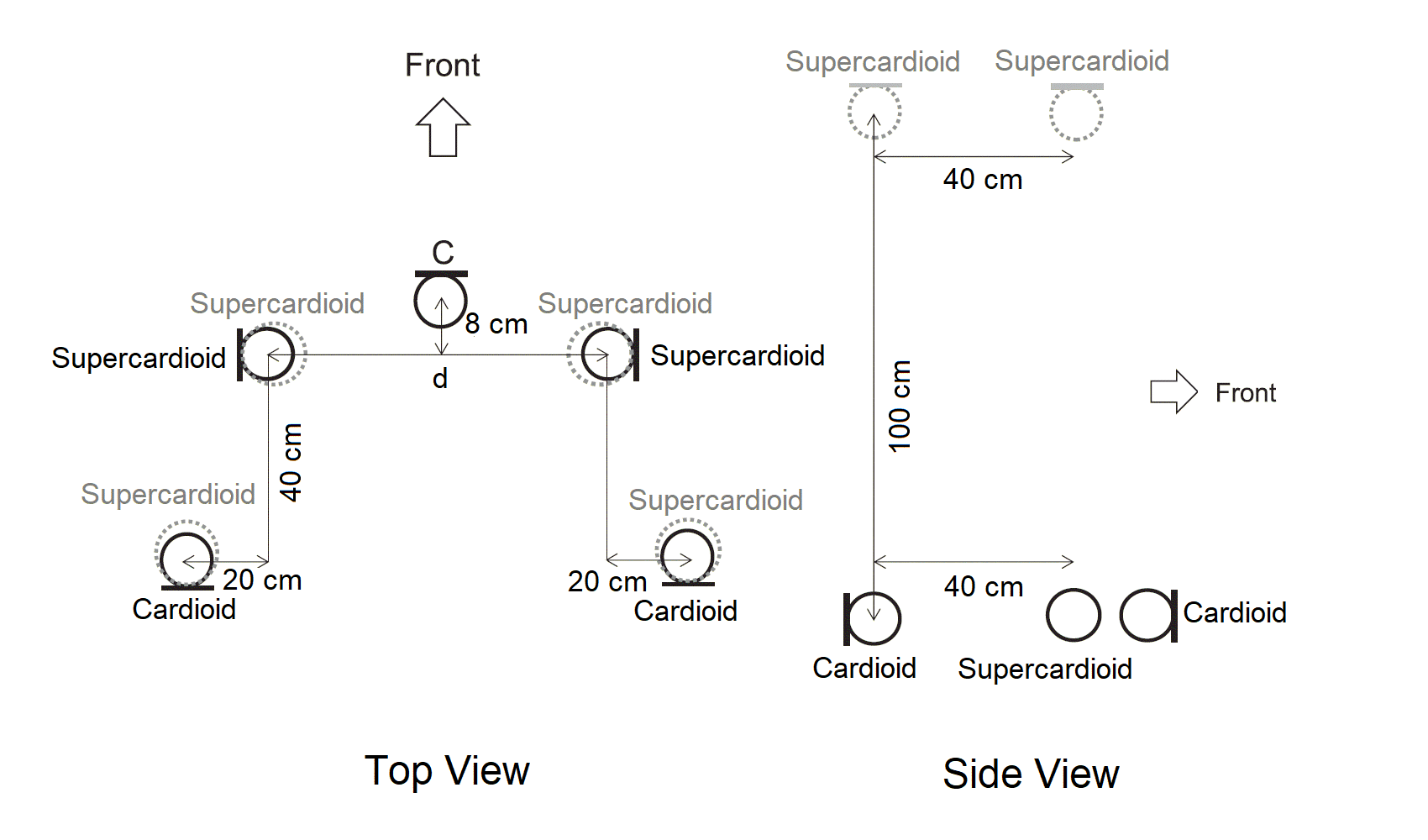
OCT-3D
The OCT-3D is a vertical extension of the five-channel OCT-Surround array. It uses four supercardioid microphones facing directly upwards and placed 1 m (3.3-ft) directly above the main layer.18 A cardioid center microphone is placed 8 cm (3 in) in front of the front row of the main layer that has two side-facing supercardioid microphones. The spacing can be varied to achieve the desired stereophonic recording angle (SRA).19
Black indicates the main layer
Grey indicates the upper layer
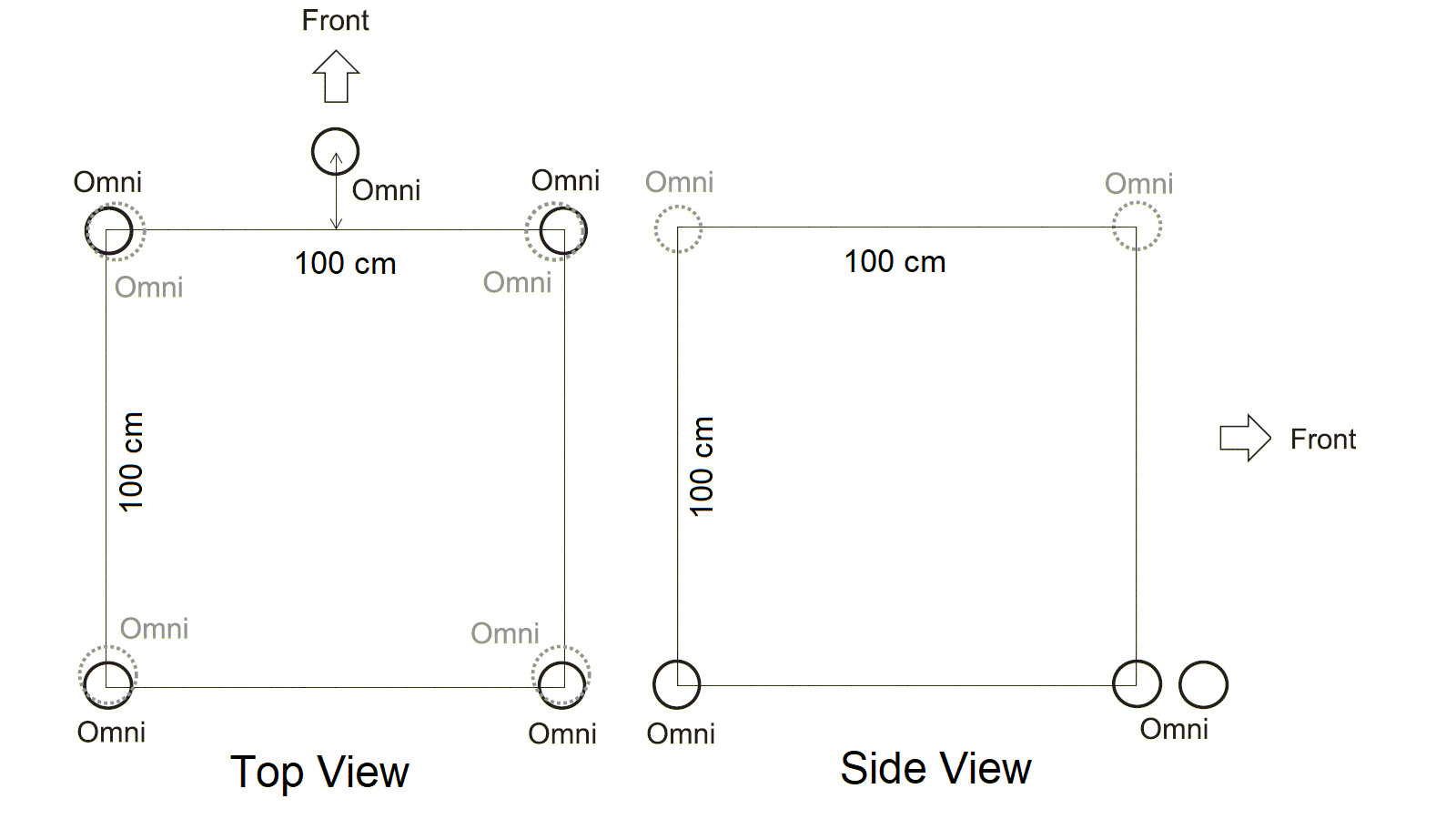
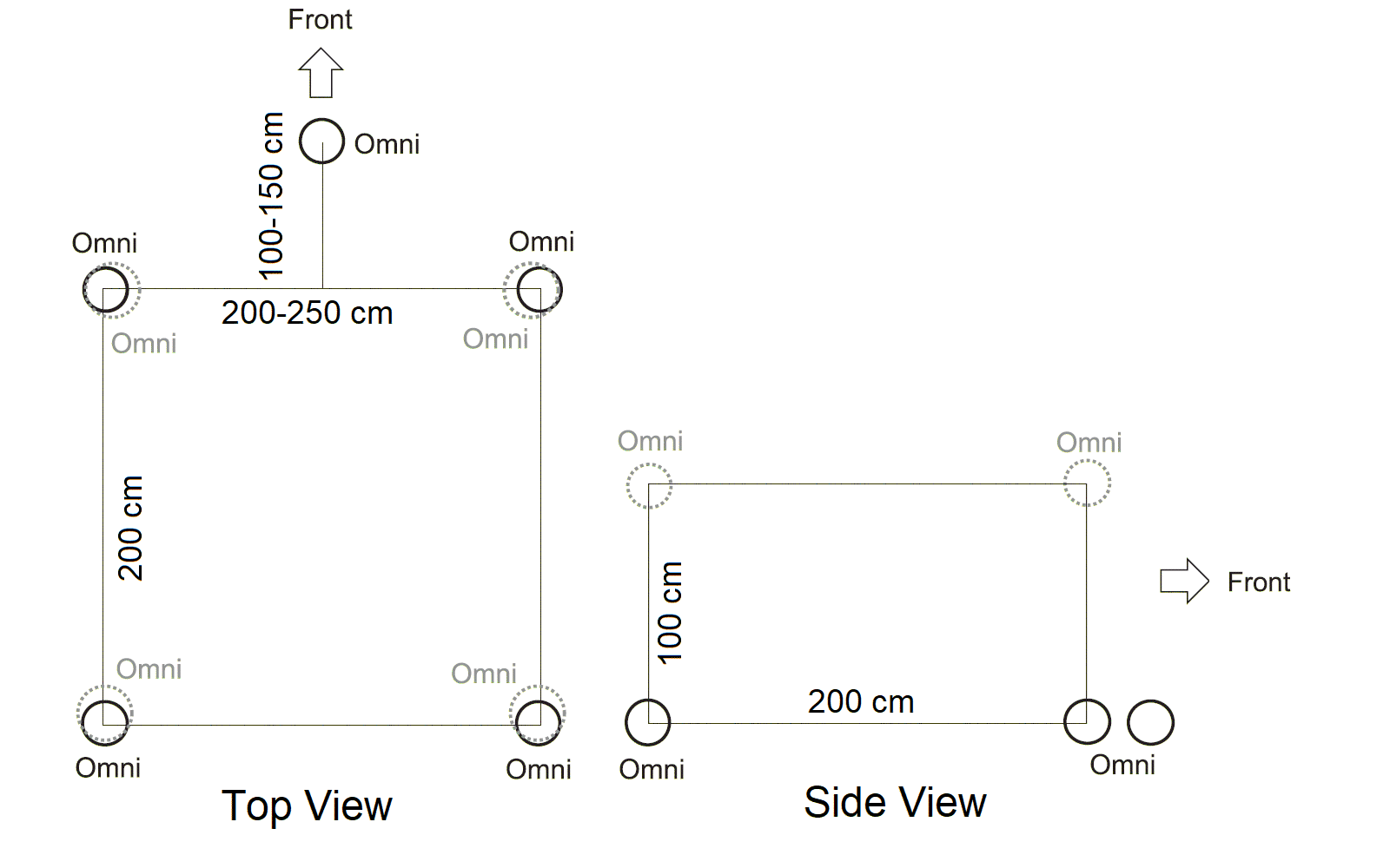
2L-Cube
The 2L-Cube is a technique developed by Morten Lindberg of the 2L record label, that uses nine omni microphones arranged in a 1-m (3.3-ft) cube structure.18 The cube size can be adjusted from 40 to 120 cm (16 to 47 in) depending upon the size of the ensemble.19
Black indicates the main layer
Grey indicates the upper layer
PCMA-3D
The PCMA-3D is an extension of the Perspective Control Microphone Array (PCMA) Surround Array. It is a horizontally spaced, vertically coincident array, developed by Hyunkook Lee based on the results of some psychoacoustic experiments. It employs five cardioid microphones for the main layer and four upward-facing supercardioid microphones for the height layer in a 1-m (3.3-ft) square.19 Each point on the array has a coincident pair of microphones. The source-to ambience ratio can be controlled by changing the mixing ratio of forward- and backward-facing cardioid microphones, which changes the perceived distance of the sound image.18
Black indicates the main layer
Grey indicates the upper layer
Decca Cuboid
The Decca Cuboid is an extension of the well-known Decca Tree, by adding two surround and four height omni microphones. It uses three widely spaced omni microphones, 2 to 2.5 m (6.5 to 8 ft) corner to corner with the center microphone 1 to 1.5 m (3 to 5 ft) out front. The rear microphones are placed 2 m (6.5 ft) back and four height microphones are 1 m (3.5 ft) above the main layer and 2 to 2.5 m (6.5 to 8 ft) apart.18
Black indicates the main layer
Grey indicates the upper layer
Decca Hybrid
One variation of the Decca Cuboid is the Decca Hybrid. It uses the same lower layer as the Cuboid, but the upper layer uses a Hamasakie Square consisting of four side-facing figure-eight microphones 1 m (3.5 ft) directly above the main layer, in a rectangle 2 m (6.5 ft) by 2 to 2.5 m (6.5 to 8 ft).19
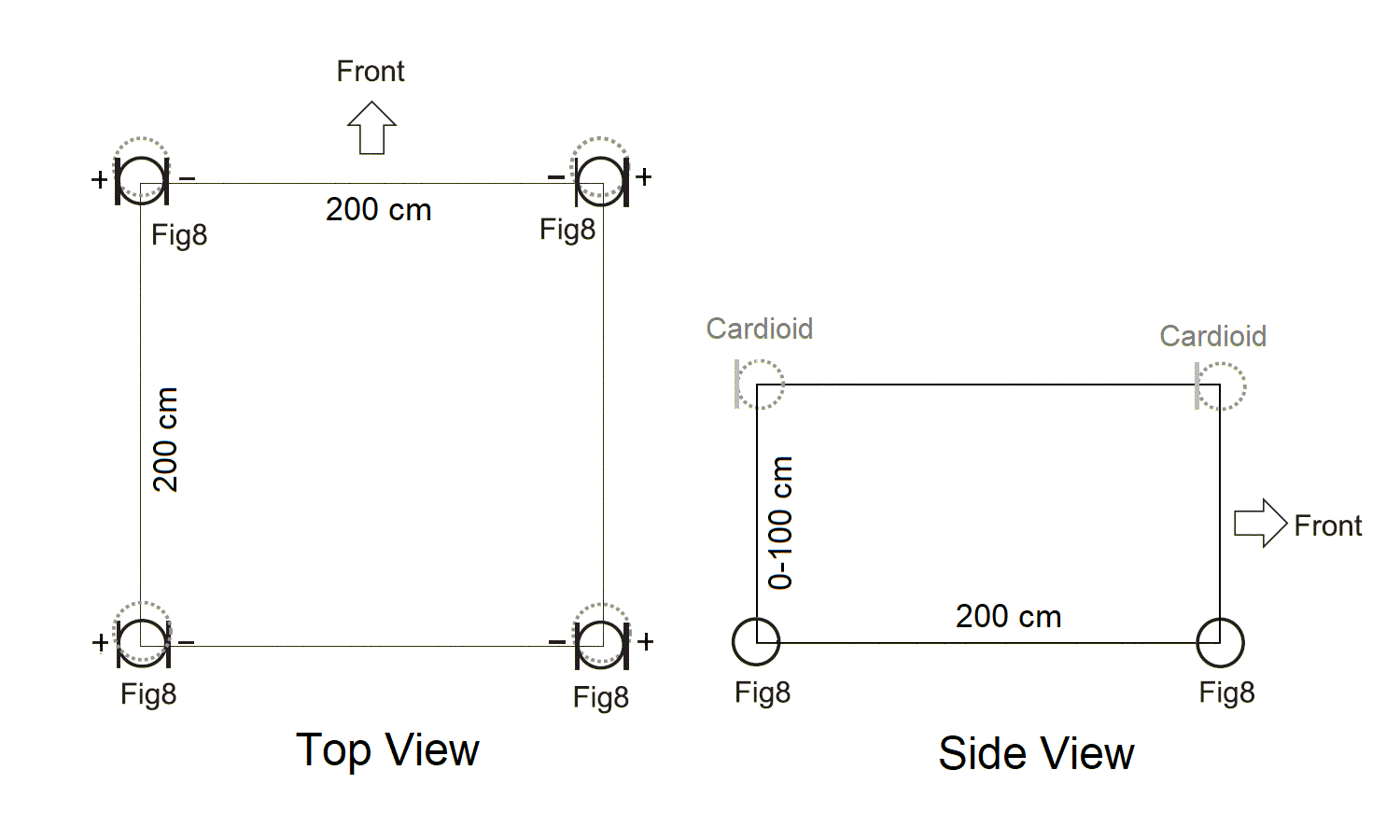
Hamasaki Cube (Hamasaki Square + Height)
The Hamasaki Cube is an extension of the Hamaski Square, developed by Kimio Hamasaki, a popular four-channel ambience capturing technique. The base layer consists of four side-facing figure-eight microphones arranged in a 2-m (6.5-ft) square. The array is augmented by four rear-facing cardioids for the height layer at 0 (vertically coincident) to 1 m (3.5 ft) above it. Originally the height layer used upward-facing supercardioids, but using cardioids facing away from the stage proved to be better at suppressing direct sounds.18
Black indicates the main layer
Grey indicates the upper layer
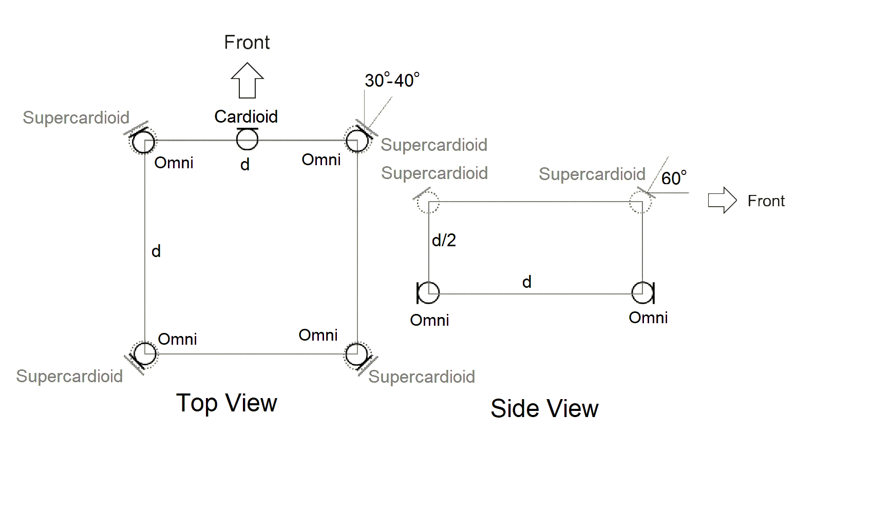
Bowles Array
The Bowles Array is a two-layer 3D array developed by David Bowles. The bottom layer consists of four omni microphones spaced on a square and angled outward. Both the distance between the mics and the angles can be adjusted to accomodate the size of the ensemble being recorded. A directional mic is positioned in the center of the front line. The height layer consists of four supercardioid mics that are half the distance above the main layer. The vertical angle is adjusted to maximize rejection of direct signals.19
Note: Most dimensions in these descriptions are given in metric units. For reference, English units are provided in parentheses rounded to the nearest inch or half foot.
Summary
When recording an orchestra or choir, it is fairly easy to try several stereo microphone techniques to see which is best for a given situation, simply by changing the spacing, the angle, or the type of microphone. However, the surround sound setups are much more complicated, using in most cases five to seven microphones that can take a considerable amount of space in a venue. The choice may be determined by the available space. However, most of the techniques to allow for some adjustment of spacing to obtain the best sound and to accommodate larger or smaller ensembles. Unlike the stereo techniques, there is no consideration of mono compatibility.
If you are making surround sound recordings in the field, many of these techniques are too unwieldy. In that case, one should consider the double M-S or one of the Ambisonic-style microphones. While these techniques may not provide as spacious a sound, they are much easier to haul around and setup.
___________________________
Last Updated: 02/10/2025
References
1Wikipedia. “Decca tree,” https://en.wikipedia.org/wiki/Decca_tree, (July 22, 2018).
2Wikipedia. “Surround Sound: Surround microphone techniques,” https://en.m.wikipedia.org/wiki/Surround_sound, (July 2018).
3MCAT Lecture, Trinity College Dublin, “Surround Microphone Techniques,” http://www.mee.tcd.ie/~gkearney/MCAT/MAT_Lecture_5_Surround_Recording_1.pdf, (July 2018).
4“Principles of the Wide Cardioid Surround Array Technique,” https://www.dpamicrophones.com/mic-university/principles-of-the-wcsa-technique, (May 2018).
5Hugh Robjohn. “Stereo Microphone Techniques Explained - Part 2,” http://www.soundonsound.com/sos/1997_articles/mar97/stereomictechs2.html, (March 1997).
6Helmut Wittek, translated by David Satz. “Microphone Techniques for 2.0 and 5.1 Ambience Recording,” http://hauptmikrofon.de/HW/Wittek%20Ambience%20%2015102013.pdf, (July 2018).
7Geoff Martin. “Microphone Techniques for Stereo and Multichannel.” http://www.sengpielaudio.com/MartinAESTutorial73.pdf (July 2018).
8Andrzej Sitek, Bozena Kostek. “Study of Preference for Surround Microphone Techniques Used in the Recording of Choir and Instrumental Ensemble.“ http://citeseerx.ist.psu.edu/viewdoc/download?doi=10.1.1.831.1273&rep=rep1&type=pdf, (July 2018).
9Bobby Owsinski. “4 Surround Sound Miking Techniques Perfect For Virtual Reality,” http://bobbyowsinskiblog.com/2016/07/27/4-surround-sound-miking-techniques/#ixzz5P15MEUg0 (July 2018).
10Toru Kamekawa. “An Explanation of Various Surround Microphone Techniques.” http://www.sanken-mic.com/en/qanda/index.cfm, (July 2018).
11“The Most Affordable Way To Record Spatial Audio,” https://decibelpeak.com/ record-spatial-audio/, (07/08/2022).
12Mirek Stiles. “How To Set Up A Spatial Audio Session,” https://www.abbeyroad.com/news/how-to-set-up-a-spatial-audio-session-abbey-roads-mirek-stiles-reds-alumnus-lifescore-2896, (07/08/2022).
13Jean-Michel Caron. “AMBEO for Loudspeakers,” https://en-us.sennheiser.com/ ambeo-blueprints-loudspeakers, (07/08/2022).
14“Applied Psychoacoustic Laboratory,” https://facebook.com/applied.psychoacoustics.lab/photos/a.804505273012765/1746378258825457/?type=3&_rdr>, (07/08/2022).
15 AMBEO Pattern, https://en-us.sennheiser.com/ambeo-pattern, (07/09/2022).
16 Helmut Wittek. “ORTF-3D: Ambience recording for 3D Audio & VR,” (07/11/2022).
17 Hyunkook Lee. “Multichannel 3D Microphone Arrays: A Review,” (07/11/2022).
18 Hyunkook Lee and Dale Johnson.
, “3D Microphone Array Comparison: Objective Measurements,” J. Audio Eng. Soc., https://doi.org/10.17743/jaes.2021.0038, (07/12/2022).
19 Justin Paterson, Hyunkook Lee, ed. 3D Audio, Routledge, 2021. (07/12/2022).
20 Bryan Martin. "Transitioning Studio Practice from Stereo to 3D: Single Instrument Capture with a Focus on the Vertical Image," A thesis submitted to McGill University, Montreal, Submitted August 2019. https://escholarship.mcgill.ca/downloads/vm40xx339.pdf (07/13/2022)
If you have questions about this article or about any other topic regarding recording studios, please contact us.

Los Senderos Studio, LLC. ★ Blanco, TX 78606
Copyright © 2008-2025 Los Senderos Studio, LLC. ★ All Rights Reserved.
Note: As an Amazon Associate this site earns commissions from qualifying purchases.